


Pantera Console Switch Repair
By John Taphorn - January 1st, 2014
Replacing the fan and light switches on the Pantera’s console was a routine exercise for daily driven Pantera’s back in the day. This was due to full amperage for the lights and evaporator blower fan flowing through them.
The problem seems to be discussed less frequently now for what I surmise to be two reasons. First, I don’t think Panteras are driven quite as frequently today. Anecdotally, I am unaware of any daily drivers in our Space City Chapter. Perhaps of greater import is the second reason; many owners are now aware of the issue caused by the full current flowing through the switches and have employed relays. The addition of a relay appears to resolve one of the switch’s internal problems, melted spades.
When I used my Pantera as a daily driver, I melted more fan switches than I did headlight switches. Although, I suppose that was due to living in the south and frequently running the AC. It had surprised me initially when I saw that the aftermarket relay kits made available did not address the fan switch. I surmise that was because the kit was sourced from California where the fan may be engaged less as it is said fewer owners maintain their AC due to a cooler and less humid climate.
I have perhaps twenty switches on my workbench that southwestern owners have presented me for repair and about half of them are fan switches with as many melted internals as headlight switches. Thus, if you run your fans for extended periods, I recommend adding relays to that circuit as well.
Of course the other motivation to replace your switches is appearance. The chrome on the plastic bezel can look a bit rough after many years or abuse. Thus, I’ll also show you how to replace only the bezel should that be your goal.
New switches currently sell for about $70 through the vendors. In contrast, you may be able to rebuild your switch with a new chrome bezel, $12 at Hall, and $10 worth of nuts and bolts and a tap.
I’ll endeavor to walk you through the process of a total rebuild. I suspect that most owners have more than one non-working switch in their personal inventory. This is a plus; as you can probably scrape together enough good parts from two non functioning switches to make an operable one.
Step 1: Bezel Removal
I have rebuilt over a dozen switches and there are two methods employed to attach the chrome bezel. One method has the bezel held in place by only the single visible horizontal rivet. The second method has the bezel held in place by an additional two vertical rivets. These vertical rivets will not be obvious until you remove the toggle button (hereafter referred to as the button). I suspect that the original switches used three rivets and depending on the remanufacturer, subsequent replacements only one. 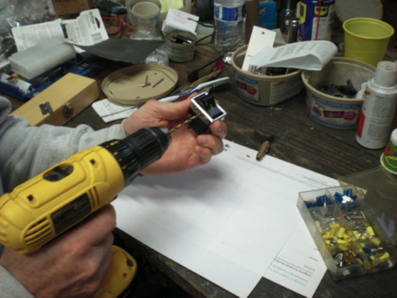
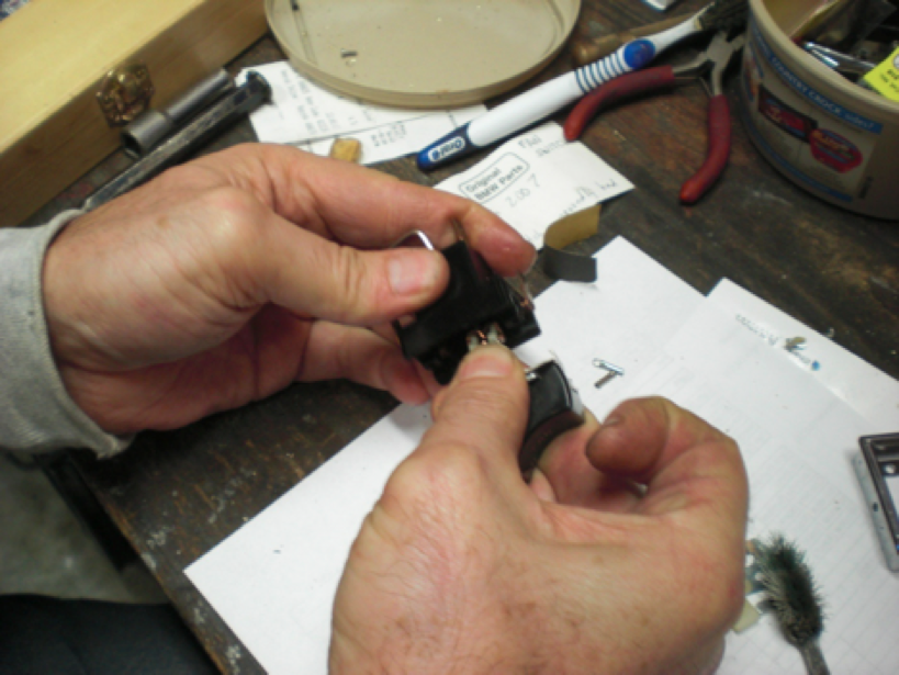
Use a drill bit of larger diameter than the long horizontal rivet to remove one of the rivet’s flanged sides. The rivet will then slide out and the button is now removable. Treat the rivet with respect as it will be used again when reassembling the switch. If you do not see two rivet flanges holding the bezel to the case after removing the button, carefully pry the bezel from the case with a screwdriver from the side. It should come off easily.
Otherwise, drill off the flanged heads of the two shorter vertical rivets from the bezel side. Now the bezel will separate from the rest of the switch. Caution, if you only intend to replace the bezel, be careful to hold the base plate, upon which the bezel sits, together with the case or a larger project is in store for you.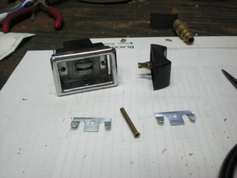
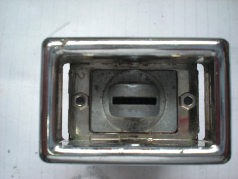
This bezel is not held in place by the two vertical rivets and can be pried off. The holes are there and the rivets holding the base plate to the case are seen behind them.
Step 2: Case Disassembly
Assuming you have removed the two vertical rivets, as you pull the base plate from the case, be mindful of the little pieces that may fall free. Now you are able to inspect the individual pieces for refurbishment or replacement.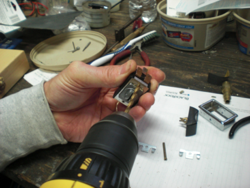
On this switch the two vertical rivets did not hold the bezel, only the base plate to the case.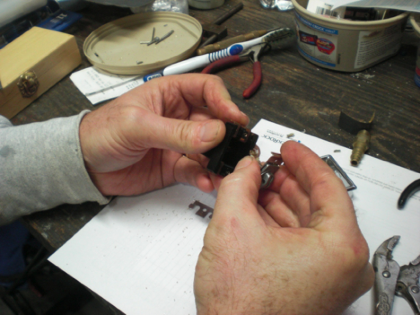
Step 3: Inspection
Areas to inspect that I have found to compromise switch performance:
The condition of the nylon spades. A good spade is pictured on the left. On the right is a melted spade. When encountering a melted spade, a second switch in inventory is handy. I have yet to see a switch where both spades were bad. I do not know where to purchase replacement spades. For that matter, if you know the company remanufacturing these switches, please share.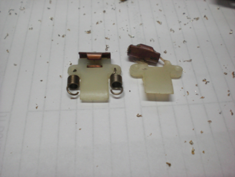
Note: The end of the spring that would attach to the base plate is open to the inside of the spade.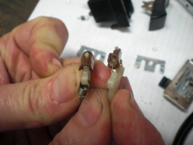
I polish the spade’s electrical contact with a wire wheel.
The rivets holding the copper tabs. The alignment of the copper tabs is critical. Rough handling when connecting or removing wire leads can loosen the rivets that hold the tabs. If the tabs are loose and able to shift, their internal alignment is compromised and electrical connection lost. They can easily be restaked with a punch while the case is separate. Occasionally, high heat warps the case causing tap misalignment. I have reused mildly warped cases after using needle nose pliers to realign the tabs.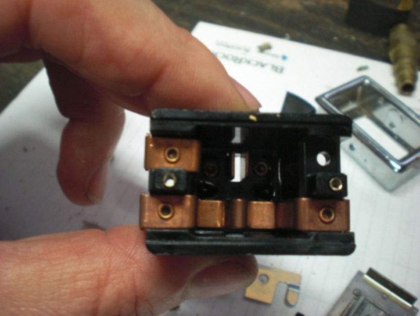
Picture of rivets holding the tabs
Check for looseness of the glide plate to the base plate. Guide plates may be re-secured with a sharp chisel and light tap on the prong with a hammer.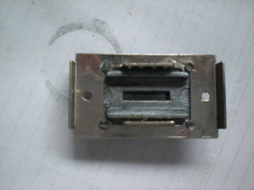
You can see marks on the bottom of the base plate where the guide plate’s prongs were re-staked.
Corrosion on the tabs and spades. I use a wire wheel on the spade’s electrical contacts; but the tabs are tougher to clean due to their close proximity to one another in the case.
I simply use a narrow wooden stick and 220 grit sand paper for the task. Sandblasting may be optimal.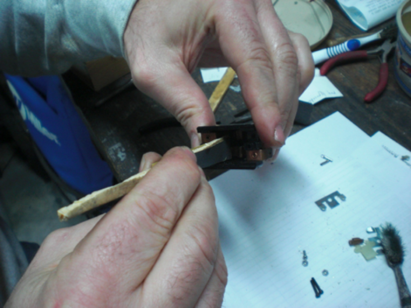
Step 4: Required supplies:
If you are only replacing the bezel, you require only B & C hardware, and then you may jump to Step 6
Two 1/2" long #2-56 thread socket head cap screws with small diameter stainless nuts. The reason for stainless nuts is that they are manufactured smaller and clearance is an issue. The socket heads fit the case perfectly. I source the nuts from my local Ace Hardware and the bolts from a local RC/railroad hobby shop.
Second, you will need a #2-56 tap. I get the tap from the hobby shop.
A 1/4 inch long #2-56 threaded bolt with a flat seat and rounded head. Again, Ace Hardware. This screw is designed to minimize interference when reinserting the rebuilt switch into the console.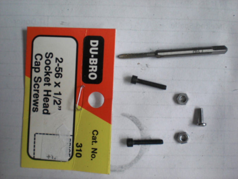
Step 5: Reassembly of Case
The result that you seek are the two spades attached to the base plate by four springs using the base plate’s center most holes while the sharp end of the spades sit in the nylon slider’s grooves. 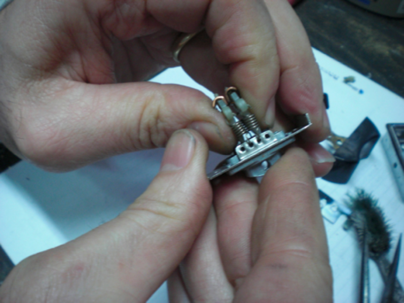
Now, how you get there depends on your own dexterity. What works best for me is to first attach the springs to the spades (note orientation) and then attach the spade/spring combo to the base. After all four springs are attached; I lean the spades to one side and slip the nylon slider under them. Then I straighten the spades into the nylon slider’s grooves. Be patient, it will eventually happen. Note that the nylon slider has two full width grooves on the spade side and two indents on the switch side. Although, I have seen nylon sliders with full width grooves on both sides. In this case, the narrower groves go on the spade side.
To get that subassembly into the case, I use a small allen wrench (the one I use for the 2-56 cap screws) inserted through the bottom of the case to help me keep the spades separated so as that they find their proper home, on each side of the tabs, when the subassembly is slid into the case. Of course, the allen wrench gets pushed out as you insert the spades and they find their home.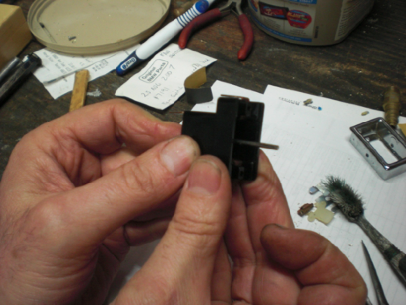
As seen in this pic, I temporarily attach the button to help keep the nylon slider to which the spades are pressed from shifting side to side during the reinsertion.
Step 6: Reattachment of the Bezel
Holding the new bezel in place on the case assembly, install the two 2-56 1/2 long cap screws from the bottom thru the case and add the nuts on the bezel side to lock it in. Yes, it is a dexterity test with only two hands.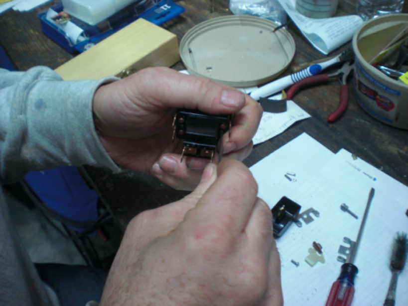
Attached bezel with two nuts
Step 7: Install the button
Reacquire the long rivet that you first removed and using your new 2-56 tap, thread the side from which you originally removed the flange. There is no need to drill the rivet to accommodate the tap.
Chamfer the end of the rivet that you just tapped to aid its insertion through the bezel and button.
When replacing the button, I find it helpful to first inspect thru the button’s receiving slot in the guide plate to confirm that the indents on the nylon slider are centered. This ensures the button is properly engaged in its centered position when you place it back in the bezel to receive the rivet.
Don't forget the side prongs that hold the switch in place in the Console. Then use the short 2-56 machine screw to complete the rivet. 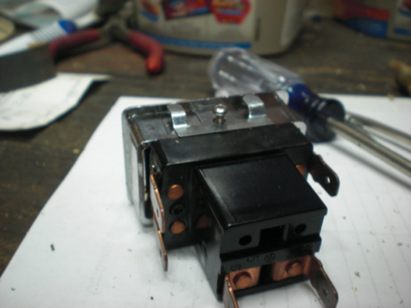
Step 8: Test with an ohm meter for continuity.
Ideally, you now have a fully functioning switch. Congratulations on the satisfaction gained from tackling the job and saving a few bucks.
You may contact me with questions at jtaphorn@kingwoodcable.com.